
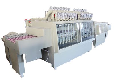
Etching Machine Ventilation and Fume Extraction: Design, Safety & Regulations
An etching machine ventilation system is a dedicated exhaust and scrubber train that captures the acid mist and HCl / NOₓ fumes generated at the etch chamber. The design has three parts: capture at the source (fume hood or lip exhaust with 100 – 150 fpm capture velocity), transport in the duct (5,000 – 8,000 fpm to keep mist in suspension), and treatment in the scrubber (packed-tower wet scrubber with NaOH or water). Compliance is governed by OSHA PEL (HCl 5 ppm ceiling, NO₂ 5 ppm ceiling) and EPA NESHAP for any line over 1,000 lbs / month of HCl.
Acid mist and chemical fumes are the most regulated part of any etching line. The chemistry does the work, but the ventilation system is what keeps the people safe and the regulator off the shop floor. This article covers the design of the ventilation system end-to-end: capture at the chamber, transport through the duct, treatment in the scrubber, and compliance with OSHA permissible exposure limits and EPA air-emission rules.
Why Ventilation Matters on an Etching Line
The etching reaction produces fumes and mist that have to be captured at the source, transported away from the operator, and treated before discharge. There are three reasons to get this right:
- Worker safety. Acid mist and HCl vapor irritate the eyes, skin, and respiratory tract. Chronic exposure causes dental erosion, bronchitis, and chemical pneumonitis. OSHA sets strict permissible exposure limits (PELs) for the most common etching fumes.
- Equipment protection. Acid mist corrodes the conveyor, the rollers, the control panel, and anything else in the room. The mist also deposits on light fixtures, switches, and ceiling tiles, leading to early failure and unscheduled maintenance.
- Regulatory compliance. Air emissions from etching lines are regulated by both OSHA (worker exposure) and EPA (ambient discharge). A non-compliant line can be shut down, fined, or both.
Fume Generation by Etching Chemistry
Different etching chemistries produce different fume profiles, and the ventilation system is sized to match the worst-case emission rate.
| Chemistry | Primary fume species | Generation rate | Hood type required |
|---|---|---|---|
| Ferric chloride (FeCl₃) | HCl vapor, FeCl₃ mist | High | Lip exhaust + side draft |
| Cupric chloride (CuCl₂) | HCl vapor, Cl₂ trace, CuCl₂ mist | High | Lip exhaust + side draft |
| Alkaline (NaOH, aluminum) | NaOH mist, H₂ (slight, from reaction) | Moderate | Side draft + canopy |
| Cupric chloride + ammonia (PCB) | NH₃, Cu(NH₃)₄ complex mist | High | Lip exhaust + side draft |
| Ferric nitrate (stainless) | NOₓ, HNO₃ vapor | Very high | Lip exhaust + scrubber with NaOH |
| Nitric / HF (titanium) | NOₓ, HF vapor | Extreme | Lip exhaust + dedicated HF scrubber |
Ferric Chloride (Most Common)
Ferric chloride etching produces HCl vapor as the main fume species. The HCl is generated by the reduction of Fe³⁺ to Fe²⁺ and the reaction of dissolved metal chlorides with the water. Generation rate: 0.5 – 2.0 mg of HCl per cm² of metal etched per minute, depending on temperature and aeration. A 1 m² sheet of 1.0 mm copper etched in 30 minutes generates 15 – 60 g of HCl vapor at the line.
Alkaline Aluminum
Alkaline aluminum etching produces a fine NaOH mist, but the main hazard is the dissolved aluminum building up in the bath. The fume generation rate is roughly half that of acid chemistry, but the mist is highly alkaline and damaging to skin and eyes. A canopy hood above the chamber is usually sufficient; side-draft is needed for higher temperature baths.
Ventilation System Design
Capture at the Source
The first principle of industrial ventilation is to capture the contaminant at the source before it can spread into the breathing zone. For an etching chamber, there are three capture options:
- Lip exhaust. A narrow slot at the chamber entrance and exit, with a high-velocity exhaust. Pulls the mist into the slot as the sheet enters and exits. Most common on conveyor etchers.
- Side draft. A vertical slot on the side of the chamber with exhaust. Good for open-top tanks and small chambers. Less common on conveyor lines because the slot is in the way of the conveyor.
- Canopy hood. A canopy above the chamber, with a wider exhaust area. Lower capture velocity, used for low-fume chemistries (alkaline aluminum). Cannot be the only hood on a high-fume acid line.
Capture Velocity Requirements
- Lip exhaust: 100 – 150 fpm at the slot opening
- Side draft: 150 – 200 fpm at the slot
- Canopy: 50 – 100 fpm at the hood face (only for low-fume applications)
- Capture velocity drops with the square of distance from the hood — keep the slot within 6 inches of the emission source
- Multiple hoods may be needed for long chambers (every 3 – 4 m)
Duct Transport
Once captured, the fume is transported through a duct to the scrubber. The duct velocity must be high enough to keep the mist in suspension (avoiding fallout and duct corrosion) but not so high that the pressure drop becomes excessive.
Duct Sizing Rules
- Duct velocity: 5,000 – 8,000 fpm (2,500 – 4,000 fpm for very large ducts)
- Below 4,000 fpm: mist fallout, duct corrosion, pooling
- Above 8,000 fpm: excessive noise, high pressure drop, particle erosion
- Duct material: PP, FRP, or stainless 316L for acid service
- Duct slope: minimum 1:100 toward the scrubber to drain condensate
- Duct cleanouts: every 10 m, plus at every direction change
Exhaust Fan Sizing
The exhaust fan provides the motive force for the system. The total pressure drop is the sum of the hood entry loss, the duct friction, the scrubber pressure drop, and the stack exit loss. For a typical conveyor etching line:
- Hood entry loss: 0.5 – 1.5 inches water column (w.c.)
- Duct friction: 0.1 – 0.3 in. w.c. per 10 m of duct
- Packed-tower scrubber: 4 – 8 in. w.c.
- Mist eliminator: 0.5 – 2.0 in. w.c.
- Stack exit: 0.3 – 0.5 in. w.c.
- Total: 6 – 12 in. w.c. for a typical line
Fan sizing example: 25 m chamber, 30 m duct run, 4 m stack, packed-tower scrubber. Total airflow: 8,000 cfm. Total pressure: 10 in. w.c. Fan motor: 8,000 × 10 × 0.000157 = 12.5 HP, plus margin → 15 HP direct-drive fan. FRP or PP fan with PTFE shaft seal for acid service.
Scrubber Design and Selection
The scrubber is the air-treatment device. It contacts the fume stream with a liquid (usually water or dilute NaOH) to absorb the acid gases. The most common scrubber types for etching lines are:
| Scrubber type | Removal efficiency | Pressure drop | Best for |
|---|---|---|---|
| Packed tower (counter-current) | 95 – 99% HCl | 4 – 8 in. w.c. | Most etching lines |
| Venturi scrubber | 95 – 99% HCl, 99%+ mist | 8 – 15 in. w.c. | High-fume or sub-micron mist |
| Impingement plate | 85 – 95% HCl | 2 – 4 in. w.c. | Low-fume, small lines |
| Cyclonic spray | 70 – 90% HCl | 1 – 3 in. w.c. | Pre-scrubber for high-fume lines |
| Dry sorbent injection | 90 – 98% HCl | Low (just duct) | Low-water applications |
Scrubber Chemistry
The scrubbing liquid depends on the fume species being removed:
- HCl removal: dilute NaOH (5 – 10%). Reaction: HCl + NaOH → NaCl + H₂O. NaOH consumption: 1.0 – 1.5 kg per kg of HCl removed.
- NOₓ removal: NaOH + sodium sulfite (Na₂SO₃). Reaction: 2 NO₂ + NaOH + Na₂SO₃ → 2 NaNO₂ + Na₂SO₄.
- HF removal: dedicated HF-rated scrubber with calcium hydroxide or potassium hydroxide. NEVER use glass-lined equipment.
- Cl₂ removal: NaOH. Reaction: Cl₂ + 2 NaOH → NaCl + NaClO + H₂O.
Scrubber Discharge
The scrubbing liquor becomes a wastewater stream. For an HCl scrubber with NaOH makeup, the discharge contains 5 – 10% NaCl and trace metals. This is regulated wastewater and cannot be discharged to a sanitary sewer without treatment. Options: send to on-site wastewater treatment, contract hauler, or recovery (e.g., NaCl recovery for chlor-alkali plants).
Regulatory Compliance
OSHA Permissible Exposure Limits (PELs)
OSHA sets the legal worker exposure limits. For an etching line, the most relevant are:
Key OSHA PELs for Etching Line Operations
- HCl: 5 ppm (7 mg/m³) ceiling
- Cl₂: 1 ppm (3 mg/m³) ceiling
- NO₂: 5 ppm (9 mg/m³) ceiling
- HF: 3 ppm (2.5 mg/m³) TWA, 6 ppm STEL
- NaOH: 2 mg/m³ TWA
- Copper dust / mist: 1 mg/m³ TWA
- Iron oxide fume: 10 mg/m³ TWA
- All values enforceable as 8-hour time-weighted averages unless noted as ceiling or STEL
EPA Air Emissions
EPA regulates the discharge to the ambient air. The applicable rule depends on the source category and the emission rate:
- NESHAP for halogen acid air emissions (40 CFR 63 Subpart NNNNN). Applies to facilities that emit more than 1,000 lbs of HCl / HF / Cl₂ per month. Requires 95% destruction efficiency or use of a wet scrubber.
- State-level rules. California (CARB), New Jersey, Texas, and a handful of other states have stricter limits, often requiring continuous emissions monitoring (CEMS).
- Title V operating permit. Larger etching operations (typically 10+ tpy of any regulated pollutant) need a Title V permit with annual emissions reporting.
Local Codes and Fire Marshal
Beyond OSHA and EPA, the local fire marshal and building department may have additional requirements:
- Scrubber and fan motor on emergency power (Class I, Division 2 area classification near the etch chamber)
- Acid-resistant flooring and secondary containment (110% of the largest tank volume)
- Eyewash and safety shower within 10 seconds (55 ft / 17 m) of the etch chamber
- Acid storage in dedicated, ventilated cabinets with acid-resistant sump
- Ventilation interlock — chamber spray cannot start if exhaust fan is not running
Common Ventilation Problems and How to Fix Them
Most ventilation problems on an etching line show up as worker complaints (smell, eye irritation) or as accelerated equipment corrosion. The five most common:
| Symptom | Cause | Fix |
|---|---|---|
| Acid mist smell in the work area | Capture velocity too low at hood, hood too far from source | Re-measure capture velocity; add lip exhaust; lower the hood |
| White deposits on light fixtures, ceiling, switches | Duct corrosion leaking mist, scrubber not removing HCl | Inspect duct for leaks; check scrubber pH and NaOH feed; check mist eliminator |
| High scrubber discharge pH, low NaOH feed | NaOH feed pump failure, level sensor stuck, line plugged | Verify pump output; clean level sensor; flush NaOH line |
| Fan motor drawing high amps | Duct blockage, scrubber packing fouled, damper closed | Inspect duct; clean packing; check damper position |
| Eyewash activation frequency (operator washing eyes after shift) | Hood draft reversed, capture lost, scrubber failure | Check fan rotation; check damper; test scrubber pH; review hood geometry |
Conclusion
The ventilation system is the part of an etching line that no one thinks about until it fails. A well-designed system — capture at the source, transport at 5,000 – 8,000 fpm, scrubber at 95 – 99% efficiency, and continuous compliance monitoring — keeps the workers safe, the equipment intact, and the regulator away. The cost of a properly designed system is 10 – 15% of the total line cost; the cost of a non-compliant one is the entire line being shut down.
Need a Ventilation System for a New Etching Line?
Send us the chamber dimensions, the chemistry, the throughput, and your facility's local air-quality rules. We will design the ventilation train — hood, duct, fan, scrubber — sized to meet OSHA PELs and EPA NESHAP.
Get a Ventilation Design