
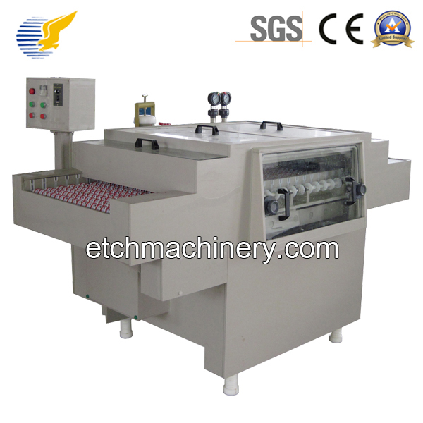
Etching Machine Capacity Sizing: How to Calculate Throughput and Chamber Length
To size an etching machine for a given throughput, you need three inputs: the part (sheet thickness and required etch depth), the chemistry (etch rate), and the target output (parts per hour or square metres per hour). The chamber length is then etch time × conveyor speed × margin. Typical conveyor widths: 300 – 1,200 mm. Typical chamber lengths: 4 – 40 m. Typical bath volumes: 200 – 6,000 L. For a worked example, a 20 m chamber running 1.0 mm aluminum at 0.04 mm/min etch rate delivers about 800 – 1,000 parts per hour for a 50 mm long part.
Sizing an etching line is one of the most common questions in the industry, and one of the most often miscalculated. The line is too long and the capital cost is wasted; the line is too short and the parts come out under-etched. This article walks through the practical formulas, the worked examples, and the design margins that turn a target throughput into a chamber length, a bath volume, a pump size, and a heater size.
The Three Inputs You Need
Before any sizing calculation, you need three numbers. Get these wrong and the line will not deliver what you expect.
Three Sizing Inputs
- Sheet thickness (or etch depth) — the depth the etchant must cut. For through-etch, this is the sheet thickness. For partial etch, this is the required depth.
- Etch rate (mm/min) — the speed at which the etchant removes metal. Depends on chemistry, temperature, concentration, and agitation. For alkaline aluminum at 50 °C: 0.03 – 0.05 mm/min/side. For ferric chloride copper at 40 °C: 0.02 – 0.04 mm/min/side. For ferric chloride stainless at 45 °C: 0.015 – 0.025 mm/min/side.
- Target throughput — parts per hour, square metres per hour, or sheets per shift. This is the output the line has to deliver.
The Core Sizing Formulas
1. Etch Time
Etch time is the simplest calculation. It is the etch depth divided by the etch rate. For a through-etch of a single sheet, the etch depth is the sheet thickness, and the etch rate is per side (since both sides etch simultaneously on a conveyor line).
Etch Time Formula
- Etch time (min) = sheet thickness (mm) ÷ etch rate per side (mm/min/side)
- Example: 1.0 mm aluminum, alkaline etch at 0.04 mm/min/side → 1.0 ÷ 0.04 = 25 min etch time
- Example: 1.6 mm copper PCB, ferric chloride at 0.03 mm/min/side → 1.6 ÷ 0.03 = 53 min etch time
- Example: 0.5 mm stainless steel, ferric chloride at 0.02 mm/min/side → 0.5 ÷ 0.02 = 25 min etch time
2. Chamber Length
The chamber length is the etch time multiplied by the conveyor speed, with a 10 – 20% design margin for entry, exit, and end-of-line safety. The conveyor speed itself is a free variable within the practical range of 0.2 – 2.0 m/min.
Chamber Length Formula
- Conveyor speed (m/min) — typically 0.5 – 1.5 m/min for conveyor etchers
- Chamber length (m) = etch time (min) × conveyor speed (m/min) × 1.15 (margin)
- Example: 25 min etch, 0.8 m/min conveyor → 23 m chamber (round to 25 m)
- Example: 53 min etch, 0.5 m/min conveyor → 30 m chamber (round to 30 m)
3. Throughput
Throughput is the conveyor speed multiplied by 60, divided by the length of the part on the conveyor. For rectangular parts, this is straightforward. For complex parts with a serpentine or pin pattern, the part length is the dimension that travels along the conveyor.
Throughput Formula
- Throughput (parts/h) = (conveyor speed (m/min) × 60) ÷ part length (m)
- Example: 0.8 m/min conveyor, 50 mm part → 960 parts/h
- Example: 1.2 m/min conveyor, 100 mm part → 720 parts/h
- Multiply by parts-per-sheet if the parts are nested (e.g., 4 small parts on a 200 mm sheet = 4 × throughput-per-sheet)
Bath Volume and Pump Sizing
The sump volume is typically 40 – 60% of the chamber volume. The pump flow rate is calculated from the spray bar flow requirement:
- Spray pressure: 1.5 – 3.0 bar at the nozzle
- Nozzle flow: 4 – 8 L/min per nozzle (depending on nozzle type)
- Typical pump flow: 100 – 800 L/min for a conveyor line
- Pump head: 20 – 35 m (covers friction losses in the spray manifold)
- Pump material: PP, PVDF, or lined cast iron for acid; cast iron or rubber-lined for alkaline
Heater Sizing
Etching chemistries are temperature-sensitive, and the etch reaction is exothermic. The heater must warm the bath at start-up, and the cooling coils must remove the heat of reaction during steady-state operation:
Heater and Cooler Sizing
- Start-up heat: V (L) × ΔT (°C) × 4.2 kJ/L/°C = kJ needed
- Example: 2,000 L bath, start at 20 °C, target 50 °C → 2,000 × 30 × 4.2 = 252,000 kJ = 70 kWh
- At 4 hours start-up time: 17.5 kW heater
- Steady-state heat of reaction: depends on etch rate and metal. Alkaline aluminum exotherms at roughly 0.6 kW per 100 g of aluminum etched per hour.
- Cooling: most lines are net exothermic. A chilled-water cooling coil in the sump is standard for alkaline aluminum lines.
Conveyor Width and Part Layout
The conveyor width is determined by the widest sheet the line will process, plus margin. Most conveyor etchers are built in 300, 400, 600, 800, 1,000, and 1,200 mm widths. The chamber walls add 100 – 200 mm on each side.
Conveyor Width Selection
- Lab line: 200 – 300 mm wide
- Small production: 400 – 600 mm
- Medium production: 600 – 800 mm
- High volume: 1,000 – 1,200 mm
- PCB sheets are typically 400 × 500 mm (small), 600 × 700 mm (medium), 600 × 800 mm (large). Conveyor width should be the largest sheet dimension + 50 – 100 mm.
Worked Examples
Example 1: LED Heat Sink Line
Sheet: 1.0 mm aluminum, 200 mm wide, parts nested 4-up on 200 mm length, target 1,000 parts/h.
- Etch rate (alkaline, 50 °C): 0.04 mm/min/side
- Etch time: 1.0 ÷ 0.04 = 25 min
- Conveyor speed: pick 0.8 m/min
- Chamber length: 25 × 0.8 × 1.15 = 23 m → 25 m
- Throughput: (0.8 × 60) ÷ 0.05 = 960 sheets/h, × 4 parts/sheet = 3,840 parts/h → exceeds target
- Final spec: 25 m chamber, 0.4 m wide conveyor, 1,200 L sump, 200 L/min pump, 25 kW heater, 15 kW chiller
Example 2: PCB Inner Layer Line
Sheet: 1.6 mm FR4 with 35 µm copper, 600 × 700 mm panels, 50 panels/h target.
- Etch rate (ferric chloride, 45 °C): 0.03 mm/min/side
- Etch time (to remove 35 µm copper from one side): about 1.2 min. But through-etch is for the unwanted copper — full chemistry time on a PCB line is longer because of loading and sidewall clearing.
- Practical etch time: 8 – 12 min depending on copper coverage and over-etch
- Conveyor speed: 0.6 m/min
- Chamber length: 10 × 0.6 × 1.15 = 7 m → 8 m chamber
- Throughput: (0.6 × 60) ÷ 0.7 = 51 panels/h → meets target
- Final spec: 8 m chamber, 0.8 m wide conveyor, 1,500 L sump, 400 L/min pump, 30 kW heater
Example 3: Decorative Stainless Steel Plate Line
Sheet: 1.2 mm stainless 304, 600 × 1,200 mm panels, 30 panels/h target.
- Etch rate (ferric chloride, 50 °C): 0.02 mm/min/side
- Etch time: 1.2 ÷ 0.02 = 60 min
- Conveyor speed: 0.5 m/min (longer etch time, lower speed for stable chemistry)
- Chamber length: 60 × 0.5 × 1.15 = 35 m → 35 – 40 m chamber
- Throughput: (0.5 × 60) ÷ 1.2 = 25 panels/h → under target
- Either accept 25 panels/h, increase conveyor speed to 0.7 m/min (chamber 48 m), or add a second chamber
Design Margins and Common Sizing Mistakes
Most etching lines that come in under target throughput are victims of one of these sizing mistakes:
Common Sizing Mistakes
Forgetting the 10 – 20% over-etch margin. A 25-min theoretical etch needs 28 – 30 min of chamber time.
Quoting the etch rate at the freshest bath. The etch rate drops as the bath loads up with dissolved metal. Size for 70 – 80% of the fresh-bath rate.
Forgetting the entry / exit zones. The first and last 1 – 2 m of the chamber are not at full spray density. Effective etch zone is 85 – 90% of chamber length.
Ignoring chemistry regeneration. A line that needs frequent chemistry changes has lower effective throughput. A regeneration system sized for steady-state operation is part of the throughput equation.
Forgetting the dryer and rinse time. The line is only as fast as its slowest section. A 25 m etch chamber with a 10 m dryer section is 35 m total, not 25 m.
Throughput Scaling: When to Add a Second Line
At some throughput, it is cheaper to add a second line than to scale up the first. The break-even depends on the chamber length, conveyor width, and chemistry:
When to Add a Second Line
- Chamber length > 35 m: physical limits and floor space start to dominate. A second line is often cheaper.
- Bath volume > 4,000 L: chemistry cost and disposal cost become significant. Two smaller baths are easier to manage.
- Two different chemistries needed: if the same shop runs PCB and metal on the same line, two lines is faster than switching chemistries every shift.
- Production redundancy: if downtime is unacceptable, two half-capacity lines is more resilient than one full-capacity line.
Conclusion
Sizing an etching line comes down to three numbers and three formulas. Get the etch rate right, multiply by the chamber length margin, and verify the throughput with the part length. Most lines that miss target throughput do so because of an over-looked margin or a fresh-bath etch rate quoted in the lab. The math is simple. The discipline is in the inputs.
Need a Sizing Calculation for Your Line?
Send us your part dimensions, sheet thickness, material, target throughput, and facility constraints. We will run the calculation and return a recommended line configuration with chamber length, conveyor width, bath volume, and pump / heater size.
Get a Sizing Calculation