
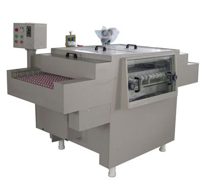
Etching Machine for Heat Sink Manufacturing: Process, Design & Equipment
A heat-sink etching machine is a conveyor spray etcher configured for high-aspect-ratio aluminum or copper parts. Most LED, EV battery and IGBT heat sinks are made by photochemical etching because the fin pattern is too thin, too dense, or too complex for stamping or skiving. The line is the same as a general aluminum etching line — alkaline chemistry, controlled temperature, double-side spray — but the artwork and the fixturing are heat-sink specific.
Heat-sink manufacturing has changed more in the last ten years than in the previous fifty. LED lighting moved to chip-on-board packages, electric-vehicle batteries moved to liquid-cooled modules, and IGBT modules for solar and wind moved to 600 A and above. All three need finer, taller, more complex fin patterns than stamping or extrusion can deliver. Chemical etching fills that gap. This article covers the etching process for heat sinks, the design rules for the fin pattern, and how to size the etching line for production.
Why Chemical Etching for Heat Sinks?
There are four ways to make a metal heat sink: extrusion, skiving, stamping, and chemical etching. Each wins in a different region:
| Process | Best for | Min fin pitch | Min fin thickness | Tooling cost |
|---|---|---|---|---|
| Extrusion | Long, simple profiles, high volume | 2.0 mm | 1.0 mm | High (custom die) |
| Skiving | Tall fins on a base, mid volume | 1.0 mm | 0.3 mm | Medium (custom tool) |
| Stamping | 2D fins on a flat sheet | 0.8 mm | 0.15 mm | High (progressive die) |
| Chemical etching | Thin, dense, complex 2D patterns | 0.4 mm | 0.08 mm | Low (artwork + phototool) |
Etching wins when the fin pattern is too dense, too thin, or too complex for stamping, and when production volume does not justify a custom extrusion die. For LED chips, EV battery cold plates, and high-current IGBT modules, etching is the default process. For high-volume simple shapes — the aluminium profile that goes on a CPU cooler — extrusion is still cheaper. The two processes complement each other.
Materials Used for Etched Heat Sinks
Aluminum 1100 / 1050
Pure aluminum is the most common etched heat-sink material. It etches cleanly in alkaline chemistry (NaOH), produces a smooth matte surface, and has high thermal conductivity. Typical thickness: 0.5 – 3.0 mm. Typical tempers: O (soft) for deep etch, H14 / H18 for thin foil with dimensional stability.
Aluminum 3003 / 5052 / 6061
Alloyed aluminum gives better mechanical strength but is harder to etch. The alloying elements (Mn, Mg, Si) leave a darker, slightly rougher surface and the etch rate is 10 – 20% slower than pure aluminum. 6061 is used when the heat sink also acts as a structural part; 3003 is the typical LED heat-sink alloy.
Copper C110 / C194
Copper is used where thermal conductivity matters more than weight — high-power IGBT modules, RF amplifiers, GPU cold plates. Copper heat sinks are etched in ferric chloride or cupric chloride chemistry. Etch rate is roughly half of aluminum, so the conveyor speed is set accordingly. Copper heat sinks are usually nickel- or tin-plated after etching to prevent oxidation.
Bonded / Clad Materials
Some heat-sink designs use a clad sheet — copper clad on aluminum, or aluminum clad on a thicker base. These are etched in a two-step process: the top layer first, then the base material. The line needs two chemistry baths and a rinse between them.
Heat-Sink Fin Pattern: Design Rules for Etching
The fin pattern drives the heat-transfer performance, and the etching process drives the achievable pattern. There is a direct relationship between fin pitch, fin thickness, sheet thickness, and etch factor:
Etch Factor for Heat-Sink Fins
- Etch factor = etch depth / lateral undercut
- For alkaline aluminum etching: typical EF = 2.0 – 2.5 (good lines), 1.5 – 2.0 (standard lines)
- Fin pitch minimum (P) = 2 × sheet thickness × (1 + 1/EF)
- Example: 1.0 mm sheet, EF 2.0: P ≥ 3.0 mm. EF 2.5: P ≥ 2.4 mm.
In practice, heat-sink designers work backwards from the thermal target. The typical LED heat sink has 0.8 – 2.0 mm fin pitch on 0.5 – 1.5 mm sheet, giving a fin density of 12 – 60 fins per cm. EV cold plates use a serpentine channel pattern etched into 1.0 – 2.0 mm aluminum, with channel width 1.5 – 3.0 mm and channel depth 0.5 – 1.5 mm.
Common Heat-Sink Patterns
- Straight fins. The simplest pattern — parallel straight fins across the sheet. Easy to etch, easy to inspect, lowest cost.
- Pin fin array. Round or square pins on a regular grid. Best for omnidirectional heat flow. Requires accurate artwork and uniform spray.
- Serpentine channel. Continuous channel that winds across the plate. Used for liquid-cooled cold plates. Channel width and corner radius must be designed for the etch factor.
- Louvered / slitted fins. Slits cut into a thicker fin to increase surface area. Common in high-power LED heat sinks.
- Custom geometry. Combinations of straight fins, pin fins, mounting holes, and edge features in one part.
Phototool and Artwork
The artwork is a 1:1 black-and-white film or a UV-direct-printed image. For high-density fin patterns (pitch below 1.5 mm), the artwork is usually laser-imaged film for sharp edge definition. Resolution: 8,000 – 12,000 dpi on the photoplotter, 25 – 50 micron line accuracy on the developed film. Phototool cost is the main artwork cost — typically a few hundred to a few thousand USD per design, and amortised over the production run.
Etching Process Parameters for Heat Sinks
Alkaline Etching (Aluminum)
Alkaline etching is the standard for aluminum heat sinks. The chemistry is sodium hydroxide (NaOH) typically 5 – 15% by weight, with dissolved aluminum building up as sodium aluminate. The reaction is exothermic, so temperature control is critical:
| Parameter | Typical range | Notes |
|---|---|---|
| NaOH concentration | 5 – 15% w/w | Higher = faster, but rougher surface |
| Temperature | 40 – 65 °C | Critical for etch rate control |
| Etch rate (1 mm Al) | 30 – 60 µm/min/side | Varies with alloy and temp |
| Etch factor | 1.8 – 2.5 | Drops at higher temperature |
| Aluminum loading | Up to 60 g/L | Limits practical bath life |
| Surface finish | Matte to satin | Can be brightened with subsequent acid dip |
Acid Etching (Copper)
Copper heat sinks are etched in ferric chloride (FeCl₃) or cupric chloride (CuCl₂) chemistry. Both work, with different operating windows:
- Ferric chloride: 38 – 42° Baumé, 30 – 50 °C. Good for general copper. Produces a clean matte surface. Easy to regenerate with chlorine gas or peroxide.
- Cupric chloride: 1.5 – 2.5 M total chloride, 0.5 – 1.0 M cupric, 30 – 55 °C. Higher etch rate than ferric at the same temperature. Slightly more complex regeneration.
- Copper etch factor: typically 2.5 – 3.5 (better than alkaline aluminum).
- Surface finish: clean matte; post-etch brightening optional.
Etch Depth Control
Heat-sink etching is a through-etch process — the etchant must cut all the way through the sheet. The critical variable is residence time in the chamber, which is controlled by conveyor speed and chamber length. Typical line speed for 1.0 mm aluminum: 0.5 – 1.5 m/min. The control loop uses sheet-thickness sensing at the entry and conveyor-speed feedback to the drive. Most lines run with a 10 – 20% over-etch to ensure complete clearing, then use an in-line optical inspection to catch under-etched parts.
Etching Line Configuration for Heat Sinks
A heat-sink etching line is a standard conveyor spray etcher, but with a few heat-sink-specific features:
- Wide conveyor with fine pitch rollers. Heat-sink sheets are usually 200 – 600 mm wide and 0.5 – 2.0 mm thick. Rollers are spaced at 50 – 80 mm to support thin sheets without sag.
- Top and bottom spray with high coverage. Both faces etch simultaneously to keep fin walls vertical. Nozzle oscillation is required for uniform coverage on a wide conveyor.
- Temperature-controlled bath. Alkaline aluminum etching is exothermic — the bath can self-heat by 5 – 10 °C across a shift. Chilled-water cooling coils in the sump hold the temperature in a ±1 °C window.
- Aluminum-tolerant pumps and fittings. Alkaline chemistry attacks standard seals and gaskets. EPDM, Viton, or PTFE seals are standard. The pump impeller is often a non-metallic material to avoid galvanic effects.
- Multi-stage rinse. A three-stage cascade rinse is typical, followed by a hot air dryer. Drag-out is significant in alkaline aluminum etching, so the first rinse stage is also a recovery bath that returns the chemistry to the etch sump.
- Fume hood with alkaline-rated exhaust. Alkaline mist is less aggressive than acid mist but still requires ventilation. The exhaust goes to a water scrubber.
Sizing the Etching Line for Heat-Sink Production
Line sizing for heat sinks follows the same rules as any conveyor etcher, with the variables being sheet size, sheet thickness, and the etch time required to cut through the sheet:
Sizing Formula
- Etch time (min) = sheet thickness (mm) ÷ etch rate (mm/min)
- Chamber length (m) = etch time (min) × conveyor speed (m/min) × 1.1 (over-design margin)
- Throughput (parts/h) = conveyor speed (m/min) × 60 ÷ part length (m)
- Example: 1.0 mm aluminum, etch rate 0.04 mm/min/side, conveyor 0.8 m/min → etch time 25 min → chamber 22 m → for 50 mm long parts, throughput 960 parts/h.
Typical Line Configurations
| Throughput target | Chamber length | Conveyor width | Bath volume | Total power |
|---|---|---|---|---|
| Lab / prototype | 3 – 5 m | 300 mm | 200 – 400 L | 15 – 25 kW |
| Small batch (200 – 500 pph) | 8 – 12 m | 400 mm | 600 – 1,000 L | 30 – 50 kW |
| Medium batch (500 – 2,000 pph) | 15 – 25 m | 600 mm | 1,500 – 3,000 L | 60 – 100 kW |
| High volume (2,000+ pph) | 25 – 40 m | 800 – 1,200 mm | 3,000 – 6,000 L | 100 – 200 kW |
The chamber length is the main sizing variable. For 1.0 mm aluminum heat sinks, a 20 m chamber is typical. For 0.5 mm LED heat sink foil, the etch time drops and the chamber can be 10 – 12 m.
Post-Etch Finishing for Heat Sinks
Etched heat sinks usually need one or more post-etch steps before they go to the customer:
- Bright dipping. A short acid dip (typically nitric / sulfuric for aluminum) restores a bright, reflective surface after alkaline etching. Improves thermal emissivity and cosmetic appearance.
- Anodizing. For aluminum heat sinks, anodizing is the most common surface treatment. It hardens the surface, improves corrosion resistance, and provides electrical insulation. Black anodizing is standard for LED heat sinks.
- Nickel / tin plating. Standard for copper heat sinks. Prevents oxidation and improves solderability for IGBT modules.
- Cleaning and degreasing. Critical for heat-sink performance — any residue on the fin surface drops heat-transfer efficiency. A deionized water rinse followed by hot-air drying is standard.
- Inspection and packaging. Optical inspection for fin completeness, burrs, and dimensional accuracy. Foam or partition packaging to protect the fragile fins.
Common Heat-Sink Etching Defects and How to Prevent Them
Most heat-sink etching problems are chemistry, artwork, or fixturing problems — not machine problems. Here are the six most common defects:
| Defect | Cause | Prevention |
|---|---|---|
| Incomplete etch (parts still bonded) | Etch time too short, temperature too low, bath exhausted | Verify etch rate daily; check NaOH concentration and temperature; check Al loading |
| Over-etched, thin fins | Etch time too long, temperature too high | Reduce conveyor speed; lower temperature; check sheet thickness tolerance |
| Tapered fin walls (non-vertical) | Spray not uniform, single-side etch, oscillation stopped | Verify both top and bottom spray; check nozzle bar oscillation; clean plugged nozzles |
| Rough / pitted surface | Temperature too high, NaOH too concentrated, alloy issue | Lower temperature; dilute chemistry; check alloy certificate |
| Residue on parts after etch | Insufficient rinse, dryer not working | Check rinse flow and pressure; check air knife |
| Burrs on fin edges | Photoresist adhesion failure | Clean and dry sheet before lamination; check lamination temperature and pressure |
Conclusion
Chemical etching is the most flexible process for heat-sink manufacturing in 2026. It handles fin pitches down to 0.4 mm, fin thicknesses down to 0.08 mm, and complex patterns that no other process can match economically. The etching line is essentially a standard conveyor alkaline etcher with heat-sink-specific fixturing, temperature control, and inspection. The art is in the artwork, the chemistry, and the post-etch finishing — not in the machine itself.
Planning a Heat-Sink Etching Line?
Send us your part drawings, sheet size, target throughput, and material. We will recommend a line configuration, an etch chemistry window, and a post-etch finishing flow.
Get a Heat-Sink Line Quote