
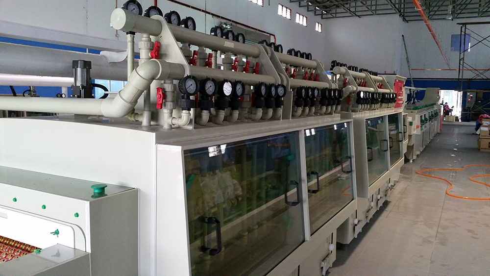
Etching Machine for RFID Antenna Manufacturing
A RFID antenna etching machine patterns copper or aluminum antennas on flexible substrates for RFID and NFC inlays. The line is roll-to-roll, runs 250 – 500 mm wide PET, paper, or aluminum web at 5 – 25 m/min, and uses ferric chloride (PET) or alkaline (aluminum) chemistry. The two-step process — pattern the antenna, then laminate to the IC chip — produces 10 million inlays per shift on a modern production line. Throughput is 50 – 500 m of web per minute.
RFID antennas are the most demanding high-volume etching application on the planet. A single roll-to-roll etching line can produce 10 million RFID inlays per shift — more than the entire global PCB production of some countries. The line is highly automated, runs 24/7, and patterns copper or aluminum antennas on PET, paper, or aluminum web at line speeds up to 25 m/min. The etching process is one of three major steps in RFID inlay manufacturing, the others being IC chip bonding and inlay conversion. This article covers the etching process in detail.
RFID Antenna Market and Production Volume
The global RFID inlay market was 35 billion units in 2024 and is growing at 12 – 15 % per year, driven by retail (apparel tagging), logistics (pallet and carton tracking), automotive (keyless entry, tire pressure), and IoT (smart packaging, asset tracking). Each inlay has one etched antenna (copper or aluminum) bonded to one IC chip. The etching step is the bottleneck of inlay production — it is the slowest of the three major steps (etching, chip bonding, conversion) and the most capital-intensive.
Volume reference
- 1 billion RFID inlays/year ≈ 3 million per day ≈ 1.5 million per shift (2-shift operation)
- A modern roll-to-roll etching line runs at 1,000 – 1,500 m of web per hour, producing 300,000 – 500,000 inlays per hour
- A single production line produces 1.5 – 2 million inlays per day, or 500 million per year
- The top 10 RFID inlay makers (Avery Dennison, Smartrac, Smart Label, etc.) operate 20 – 80 such lines worldwide
RFID Antenna Substrates
| Substrate | Conductor | Application | Etching chemistry |
|---|---|---|---|
| PET film (50 – 100 µm) | Electrodeposited (ED) copper 9 – 18 µm | UHF RFID, NFC, smart card | Ferric chloride (FeCl₃) |
| Paper (50 – 80 g/m²) | ED copper 9 – 12 µm with adhesive backing | Apparel hangtag RFID, pallet label | Ferric chloride |
| Aluminum foil (30 – 50 µm) | Pure aluminum 1050 or 1100 | UHF RFID, single-use logistics tag | Alkaline (NaOH) |
| PI film (12 – 25 µm) | RA copper 9 – 12 µm | High-end RFID, aerospace | Cupric chloride or alkaline ammonia |
| Coated paper (50 – 80 g/m²) | Aluminum vapor-deposited 0.5 – 1 µm | Single-use logistics, retail | Alkaline (gentle) |
RFID Antenna Etching Process
Step 1: Web Cleaning
The incoming web is unwound from a 500 – 1,000 m roll and passes through an in-line cleaning station. For PET web, the cleaning is a soft brush + DI water rinse. For paper, a light alkaline cleaning (0.5 % Na₂CO₃, 30 °C) removes surface contaminants. The web is dried with hot air at 60 – 80 °C.
Step 2: Photoresist Lamination
Dry-film photoresist (DFR) at 25 µm is laminated at 100 – 110 °C, 1.5 – 2.5 bar pressure, 5 – 20 m/min. The DFR is slit to web width, with alignment holes matching the web sprocket holes. Lamination is the rate-limiting step of the line — most modern R2R etchers run DFR lamination at 10 – 25 m/min, while the etching chamber itself runs at 5 – 20 m/min.
Step 3: Exposure
Collimated UV LED exposure at 80 – 120 mJ/cm². The artwork is a 1:1 glass or film photomask with the antenna pattern, repeated across the web. A modern exposure station has 4 – 8 UV lamps in series, exposing 1 – 2 m of web per pass. Line speed is matched to DFR lamination (10 – 20 m/min).
Step 4: Development
1.0 – 1.5 % sodium carbonate at 30 °C, 20 – 40 seconds. The exposed DFR washes away, leaving the antenna pattern as bare copper/aluminum. Dwell time is short (because the DFR is thin) and the developing chamber is 1 – 2 m long.
Step 5: Etching
Two chemistries, depending on substrate:
Etching chemistry for RFID
- Ferric chloride (FeCl₃) for PET / paper substrates — etch rate 15 – 25 µm/min/side at 35 – 45 °C, pH < 1. The bath is regenerated with chlorine or peroxide. Sludge is high (Fe(OH)₃) — requires dedicated waste treatment.
- Alkaline (NaOH) for aluminum substrates — etch rate 20 – 40 µm/min at 40 – 55 °C. Lower sludge but attacks PET (so PET and aluminum cannot share a line).
- Etch factor 1.5 – 2.0 (typical). For RFID antennas, the minimum trace width is 0.3 – 0.5 mm, so the etch factor is not the limiting factor.
- Line speed 5 – 25 m/min, depending on copper thickness and bath concentration. Most modern lines run 10 – 15 m/min for 9 – 12 µm copper.
Step 6: Stripping and Cleaning
The remaining DFR is stripped in 1.5 – 3 % NaOH at 35 – 45 °C, 20 – 40 seconds. The web is then rinsed in cascade DI water and dried with hot air at 60 – 80 °C. The web moisture at exit must be < 100 ppm to prevent delamination in the next step.
Step 7: Slitting and Re-Winding
The etched web is slit to the final inlay width (typically 30 – 100 mm) and re-wound on a take-up reel. Multiple inlay lanes are produced in parallel from one wide web — a 300 mm web typically produces 6 – 12 lanes of 30 – 50 mm inlay strips.
RFID Etching Line Configuration
A modern RFID etching line is a fully integrated roll-to-roll system:
- Pay-off and accumulator. 1,000 m web capacity, with 30 – 50 m accumulator for continuous operation during web change.
- Tension control. ±0.5 N closed-loop tension on every section. Critical for registration — the antenna pattern must align with the chip bond pads to within ±50 µm.
- Pre-cleaning. Soft brush + DI water + hot air dryer.
- DFR lamination. 2 – 3 m heated nip, 100 – 110 °C, 1.5 – 2.5 bar, 5 – 25 m/min.
- Exposure. 4 – 8 UV LED lamps, 80 – 120 mJ/cm², 10 – 20 m/min.
- Developing + spray rinse. 1 % Na₂CO₃, 30 °C. Dwell 20 – 40 s.
- Etching chamber. 2 – 4 m, top and bottom spray, oscillation, ferric chloride at 40 °C, 5 – 20 m/min.
- Stripping + cascade rinse. 1.5 – 3 % NaOH, 40 °C, 20 – 40 s. Three-stage cascade DI water rinse.
- Hot air dryer. 60 – 80 °C, 5 – 10 m/s air velocity. Moisture at exit < 100 ppm.
- Slitter + re-wind. Multiple inlay lanes from one web, 30 – 100 mm wide. Take-up reel 500 – 1,000 m.
- Inline vision inspection. Line-scan camera checks trace width, shorts, opens, and registration.
Common RFID Etching Defects and How to Prevent Them
| Defect | Cause | Prevention |
|---|---|---|
| Antenna trace shorts (copper bridges) | DFR void from dust or wrinkle | Clean room DFR lamination (Class 1,000); visual inspection of lamination |
| Trace opens (broken traces) | Etch time too long, ferric chloride too aggressive | Reduce conveyor speed; check FeCl₃ concentration hourly |
| Trace width out of spec | Etch factor too low, spray not perpendicular | Adjust spray bar angle; check bath chemistry |
| Antenna lift-off from substrate | Poor DFR adhesion, web moisture too high | Pre-dry web before lamination; check DFR lamination temp & pressure |
| Substrate attack (PET) | Alkaline chemistry spillover; or FeCl₃ pH too high | Use dedicated line for PET; keep FeCl₃ pH < 1 |
| Web tracking error (lateral shift) | Web tension not balanced; roller alignment off | Recalibrate web tracking; check roller alignment |