
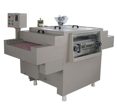
Etching Line Facility Planning: Site, Utilities, Layout & Cost
An etching line facility requires 300 – 800 m² of floor space (depending on throughput), 200 – 600 kW of three-phase power, 5 – 20 m³/day of DI water, 500 – 2,000 m³/h of exhaust ventilation, and a dedicated wastewater treatment system with 20 – 50 m³/day capacity. Site selection should be in an industrial park with existing chemical-waste infrastructure. Total facility cost is typically 500,000 – 2,000,000 USD, with the etching line itself accounting for 40 – 60 % of the total.
Planning an etching line facility is more than just buying the equipment. The line needs a purpose-built space with the right utilities, drainage, ventilation, chemical storage, safety zones, and wastewater treatment. A poorly planned facility leads to higher operating cost, regulatory trouble, and worker safety incidents. This article covers the major decisions in planning an etching line facility — site selection, utility requirements, layout, drainage, safety, and budget estimation.
Site Selection
The first decision is where to build the facility. The most important factors are:
- Industrial park zoning. Choose an industrial park that allows chemical manufacturing. Residential zones are not allowed. The park should have a centralized wastewater treatment plant (CWWTP) or allow on-site treatment.
- Chemical infrastructure. Proximity to chemical suppliers (NaOH, FeCl₃, CuCl₂, HCl) reduces logistics cost. A 100 km radius typically has 3 – 5 suppliers for each chemical.
- Power grid. Three-phase 380 V (China, EU) or 480 V (US) power at 500 kVA or more. The site should have a dedicated transformer for the etching line, not shared with the rest of the facility.
- Water source. Industrial water at 5 – 20 m³/day. DI water system (mixed-bed ion exchange or RO) is required. Source water TDS should be < 200 mg/L for the DI system to work efficiently.
- Wastewater discharge permit. The site must have a permit from the local environmental protection bureau (EPB) for discharge of treated wastewater. The permit specifies daily discharge limit, effluent quality standards, and self-monitoring requirements.
- Ventilation and exhaust. The site must have space for exhaust stacks (typically 10 – 15 m tall) and the ability to vent the exhaust through a scrubber before discharge. Local regulations may limit stack height and discharge rate.
- Logistics. Proximity to highways or rail for raw material and finished goods transport. Truck access for 40-foot container loading.
Utility Requirements
| Utility | Specification | Typical demand | Notes |
|---|---|---|---|
| Three-phase power | 380 V / 50 Hz (China, EU) or 480 V / 60 Hz (US), 500 kVA dedicated transformer | 200 – 600 kW | Etching line: 100 – 200 kW. Auxiliaries (vacuum, exhaust, DI water, lighting): 100 – 400 kW |
| Industrial water (cooling, rinsing pre-treatment) | TDS < 500 mg/L, 2 – 4 bar, DN50 pipe | 10 – 50 m³/day | Counter-current cooling tower or chiller if no cold water |
| DI water (rinsing) | Resistivity > 10 MΩ·cm, 1 – 2 bar, DN25 pipe | 5 – 20 m³/day | Mixed-bed ion exchange or RO + mixed-bed |
| Compressed air | 0.5 – 0.7 MPa, oil-free, dewpoint -20 °C, DN25 pipe | 5 – 20 m³/min | For pneumatic actuators, conveyor drive, blow-off |
| Exhaust ventilation | Polypropylene (PP) or PVDF duct, 0.5 – 1.0 m/s duct velocity, water scrubber | 500 – 2,000 m³/h | Per etching chamber; mandatory for acid and alkaline mist |
| Natural gas (optional) | For hot air dryer or annealing | 20 – 100 m³/h | Optional — most modern lines use electric heat |
| Floor drain | Acid-resistant (PP or HDPE) drain, 100 mm diameter, slope 1 – 2 % | 5 – 50 m³/h peak | Separate drains for chemical, rinse, and clean (foot/hand wash) water |
| Emergency shower and eyewash | ANSI Z358.1 or equivalent, in 10 m of every workstation | — | Mandatory in most jurisdictions |
Facility Layout
A typical etching line facility has 4 distinct zones:
4 facility zones
- Zone 1: Receiving and pre-treatment. Material receiving, storage, and pre-treatment (cutting, brushing, cleaning). Floor area 50 – 100 m². Adjacent to material warehouse. Forklift access.
- Zone 2: Etching line. The etching line itself, plus developing, stripping, drying, and post-etch inspection. Floor area 100 – 300 m². Open layout with conveyor aisles 1.2 – 1.5 m wide. Floor is acid-resistant (vinyl or epoxy with acid-resistant grout). Floor slope 1 – 2 % toward drains. Drip trays under each chemical bath.
- Zone 3: Chemical storage and preparation. Separate room, 30 – 60 m², with chemical-resistant flooring, secondary containment (110 % of largest tank), and ventilation (10 – 20 air changes/hour). Acids and alkalis stored in separate sub-areas. Oxidizers (H₂O₂, NaClO) stored separately from organics.
- Zone 4: Wastewater treatment. Outdoor or separate indoor area, 50 – 150 m². Equalization tank, pH adjustment, clarifier, sludge dewatering, and treated water monitoring. Outdoor installation is preferred for odor and safety, with weather protection.
Additional spaces: office (30 – 60 m²), quality control lab (20 – 40 m²), locker room and break room (40 – 80 m²), electrical and control room (20 – 40 m²), chemical waste storage (20 – 40 m²).
Drainage Design
Drainage is one of the most critical design elements. Mistakes lead to leaks, contamination, and regulatory violations. Key principles:
- Three separate drain systems. (1) Chemical drain (from etching line, acid and alkaline) — PP or HDPE pipe, leads to wastewater treatment. (2) Process rinse drain (from rinses) — can be combined with chemical drain or separated, depending on the chemistry. (3) Clean drain (from foot wash, floor cleaning, hand wash) — leads directly to municipal sewer.
- Floor slope 1 – 2 %. Floor slopes toward drains. No flat spots where chemical can pool.
- Acid-resistant grout and flooring. Epoxy floor with acid-resistant grout, or vinyl sheet flooring with welded seams. Avoid ceramic tile (grout is attacked by acid) and bare concrete (absorbs chemicals).
- Drip trays. Each chemical bath has a drip tray of 110 % volume. Drip trays are PP or PE, with leak detection.
- Floor drains 100 mm diameter, every 6 – 10 m. Grates are PP or stainless. No PVC (degraded by acid and UV).
- Sight glass and sampling port. Every drain junction has a sight glass to detect clogs. Sampling ports for compliance monitoring.
Safety Zones and Emergency Equipment
The etching facility has 3 safety zones with different PPE requirements:
Safety zones
- Green zone (low risk). Material receiving, finished goods storage, office. Standard PPE (safety shoes, safety glasses).
- Yellow zone (medium risk). Pre-treatment, etching line, drying. PPE includes chemical-resistant apron, gloves, face shield, safety glasses, and respiratory protection for chemical handling. Emergency shower and eyewash station within 10 m.
- Red zone (high risk). Chemical storage, wastewater treatment, sludge handling. Same PPE as yellow zone plus full-face respirator for chemical splash risk. Mandatory buddy system — never work alone. Emergency shower within 10 m.
Budget Estimate
A typical 1 m³/day PCB etching line facility budget is shown below. The numbers are for a turn-key facility in a Chinese industrial park, mid-2026 prices.
| Item | Cost (USD) | % of total |
|---|---|---|
| Etching line equipment | 400,000 – 800,000 | 45 – 55 % |
| Wastewater treatment system | 80,000 – 200,000 | 10 – 12 % |
| Exhaust and ventilation system | 40,000 – 100,000 | 5 – 7 % |
| Building and civil works (renovation) | 100,000 – 250,000 | 12 – 18 % |
| DI water system | 30,000 – 60,000 | 3 – 4 % |
| Electrical and control | 40,000 – 100,000 | 5 – 7 % |
| Chemical storage and dosing | 20,000 – 50,000 | 2 – 3 % |
| Safety equipment (PPE, showers, fire) | 10,000 – 30,000 | 1 – 2 % |
| Installation, commissioning, training | 50,000 – 100,000 | 5 – 7 % |
| Permits, environmental study, certification | 20,000 – 50,000 | 2 – 3 % |
| Contingency (10 %) | 80,000 – 170,000 | 10 % |
| TOTAL | 870,000 – 1,910,000 | 100 % |